

The following diagram is the circuit diagram of 20 band stereo graphic equaliser which will controlling the audio signal in specific frequency range.
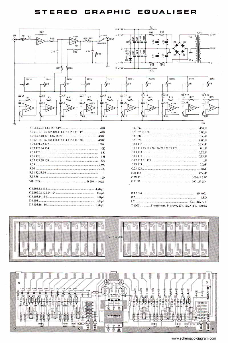
This circuit must be connected before the amplifier circuit. For maximum performance, you may use high quality electronic component such as metalfilm resistor, MKM capacitor (nonpolar), tantalum capacitor (bipolar). You may replace the power supply module with regulated and stabilized power supply or just add IC LM7815 after R35 and IC LM7915 after R36.
No comments:
Post a Comment