Sunday, June 26, 2011

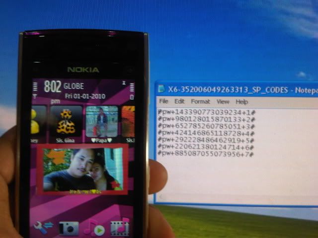
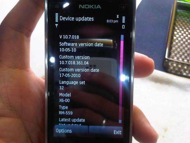
X6 SHOW KOREA unlock done VIA BRUTE-FORCE

tools to be needed :
MXBOX activated Or ATF activated
UFCv2
SUPER PC

ACTION TAKEN: Read sha file or cod file. then you need to input the sha file or cod file in mxbox or atf activated then do Brute-forcing to calculate the IMEI of the phone. after calculating the imei, Now is the time to manual input the code in phone.


DONE!


Samsung Hard Reset I607 And Samsung i900 Omnia

Samsung Hard Reset I607 And Samsung i900 Omnia

Samsung I607


Hard Reset

To perform a manual Hard Reset, press the Up Navigation key and the [Power] key.


Samsung i900 Omnia


Reset

hold the Call and Cancel buttons, poke the soft reset hole and the reset screen shall show up.


By the way, this hard reset does not erase the 16GB memory. To reset everything, you could use the software hard reset by going to Settings > Hard Reset. There is also option to format the storage card.

HTC Glofiish X500 (hard reset)


Hold the “Power Button” and press the “Reset Button” with the stylus, and release both buttons simultaneously.
Next, hold the End Button until the system inquiry screen is displayed, then release the End Button and answer the
question(s).

HTC M600 (hard reset)

M600


HARD RESET
(1) Press Power Button and Reset Button together and release them at the same time.
(2) Immediately before device starts to reboot, press and hold End Call Button for approximately 15 seconds until the "Erase all data and loads defaults ?" screen appears.
(i) If you wish to restore your device to the factory settings with the default WM5 OS and erasing all user data and user programs, press and hold the Speedial Button for about 5 seconds until the default "No" changes to 'Yes".
(ii) If you want to retain your user data and programs, do nothing and the system will choose the options "No" by default before rebooting your device.

dell-axim-x3-standard (hard reset)


To perform a hard reset:

Press and hold the power button.
With the stylus, hold the reset button for about 2 seconds.
Follow the instructions on the screen.

Some HTC Hard Reset Here

cingular_8125_hard_reset


hard reset


Press and hold the Comm Manager button and Voice Command button on the device.
Keep the two buttons pressed, and at the same time, use the stylus to lightly press and hold the RESET button.

Tuesday, June 21, 2011

http://bux2get.com/_4202bfd5.htm


If you unlock lots of BlackBerry Phones with us then you know we offer different Instant Calculators (Old Security & New Security) that give many codes, but there was a way to get ONE Working Code by using our tool “BlackBerry Calculator NEW Security - MEP (Instant)“, the only problem was to use this tool we requested you provide us with the IMEI + MEP-xxxx-xxx. BUT to get the MEP you need to read the phone by Cable usually. So NOW we are glad to provide you a solution to get your MEP-xxxxx-xxx without Cable making life easier for you and your customers!!

How to read the MEP without Cable

First step is to access to the “Help Me” menu, to do so, on the main screen of the phone hold the following keys : ALT CAPS H (at the same time)

Note: For Pearl and other Sure-type phones press and hold the ALT key (Bottom left) and type E A C E, for Storm, hold the BACK arrow, and tap the screen in the following areas: TOP LEFT, TOP RIGHT, TOP LEFT, TOP RIGHT.

You should be presented with a screen like the one shown below:


Type the PIN, App Version and Uptime in the form below:
Click Here for Blackberry eScreen Keygen


Click Here for Blackberry eScreen Keygen

Press “Get my Key” and our Calculator will generate a code:


Click Here for Blackberry eScreen Keygen

Now simply type the KEY directly on to that screen. Nothing will appear when typing. For numbers hold the ALT key when typing. Now you should be in the engineers menu - if you are not please try again ensuring the data you entered is EXACTLY as displayed. If you close the screen ensure you change the Uptime on the form. Navigate to ‘OS Engineering Screens‘ as shown below:

http://bux2get.com/_4202bfd5.htm
Now scroll down to ‘Device Info’ and then scroll down until you see MEP-XXXXX-XXX’ as shown below:


That’s your MEP! Please send it to us.

Monday, June 20, 2011

6.20, 6.35 and 6.39 PRO-B7 released!

full new release - PRO-B7 Official!


Here's the changelog:

[!] Fixed NODRM Engine (DDF012 DLC Costume Bug)
[!] Improved Inferno Game Compatiblity (GTA China Town, Corda2f, etc.)
[!] Updated scePower_driver NID Resolver
[!] Added Configuration Reset on PRO Update
[!] Added DA psp-packed user module support
[+] Added UMD VIDEO / GAME XMB Mount Feature (No UMD required, allows for Game Updates)
[+] Added Custom IPL Flasher for 6.39 PRO (1g, 2g hackable mainboard permaflash)
[+] Added non latin1 ISO filename support
[+] Added memory stick speedup option
[+] Added ISO cache option (available in Inferno and NP9660)


6.20 PRO-B7

6.35 PRO-B7

6.39 PRO-B7

Power Diode For Solar Power Systems

Posted: 13 Jun 2011 09:01 AM PDT
Apart from the sun, solar power systems cannot work without a reflow protection diode between the solar panel and the energy store. When current flows into the store, there is a potential drop across the diode which must be written off as a loss in energy. In the case of a Schottky diode, this is not less than 0.28 V at nominal current levels, but will rise with higher ones. It is clear that it is advantageous to keep the energy loss as small as possible and this may be achieved with external circuitry as shown in the diagram. The circuit is essentially an electronic switch consisting of a high precision operational amplifier, IC1a, a Type OP295 from Analog Devices, and a MOSFET, T1.

This arrangement has the advantages over a Schottky diode that it has a lower threshold voltage and the lost energy is not dissipated as heat so that only a small heat sink is needed. When the potential at the non-inverting input of the op amp, which is configured as a comparator, rises above that at the inverting input, the output switches to the operating voltage. The transistor then comes on, whereupon light-emitting diode LD1 lights. Diode D3 clamps the inputs of IC1a so that the peak input voltage cannot be greater than half the threshold voltage, provided the values of R3 and R4 are equal.

Power Diode For Solar Power Systems circuit diagram
The op amp provides very high small-signal amplification, a small offset voltage, and consequent fast switching. The MOSFET changes from on to off state and vice versa at drain -source voltages in the microvolt range. In the quiescent state, when UDS is 0 V, the transistor is on, so that LD1 lights. The operating voltage (C–A) may be between 5 V (the minimum supply for the op amp and the input control potential, UGS, of the transistor) and 36 V (twice the zener voltage of D1). Zener diode D1 protects the MOSFET against excessive voltages (greater than ±20 V). Diode D3 and resistors R3 and R4 halve the potential across the inputs of the op amp.

This ensures that operation with reversed or open terminals is harmless. The substrate diode of the MOSFET is of no consequence since it does not become forward biased as long as the forward voltage, USD, of the transistor is held very low. The on -resistance, RSD(on), of the transistor is only 8 mΩ and the transistor can handle currents of up to 75 A. When the nominal current is 10 A, the drop across the on-resistance is 80 mV, resulting in an energy loss of 0.8W. This is low enough for a SUB type with a TO263-SMD case to be used without heat sink. When the current is 50 A, however, it is advisable to use a SUP type with a TO220 case and a heat sink since the transistor is then dissipating 12.5 W.

Even then, the voltage drop, USD = 0.32 V is significantly lower than that across a Schottky diode in the same circumstances. Moreover, owing to the high precision of IC1a, a number of transistors may be used in parallel. The circuit proper draws a current of 150 µA when only one of the op amps in the OP295 is used. An even lower current is drawn by the alternative Type MAX478 from Maxim. However, the differences between these two types are only relevant in the low current and voltage ranges. Both have rail-to-rail outputs that set the control voltage accurately even at very low operating voltages.

This is important since the switch-on resistance of MOSFETs is not constant: t drops significantly with increasing gate potentials and decreasing temperature. A experimental circuit may use an LM358 op amp and a Type BUZ10 transistors, but these components do not give the excellent results just described.
Sunday, June 12, 2011

Gentle Battery Regulator

This small but very effective circuit protects a lead-acid battery (12-V solar battery or car battery) against overcharging by a solar module when the incident light is too bright or lasts too long. It does so by energizing a fan, starting at a low speed when the voltage is approximately 13.8 V and rising to full speed when the voltage exceeds 14.4 V (full-charge voltage). The threshold voltage (13.8 V) is the sum of the Zener diode voltage (12 V), the voltage across the IR diode (1.1 V), and the base-emitter voltage of the 2N3055 (0.7 V). In contrast to circuits using relays or IC amplifiers, the circuit has a gradual switching characteristic, which avoids relay chatter and the constant switching on and off near the switching point produced by a ‘hard’ switching point.

Gentle Battery Regulator circuit diagram
The circuit does not draw any current at all (auto power-off) below 13 V. Pay attention to the polarization of the Zener and IR diodes when building the circuit. The transistor must be fitted to a heat sink, since it becomes hot when the fan is not fully energized (at voltages just below 14 V). A galvanized bracket from a DIY shop forms an adequate heat sink. The indicated component values are for a 10-W solar module. If a higher-power module is used, a motor with higher rated power must also be used. The circuit takes advantage of the positive temperature coefficient of the lamp filament. The filament resistance is low at low voltages and increases as the voltage rises. This reduces the speed of the fan to avoid generating an annoying noise level. The lamp also provides a form of finger protection.
If you stick your finger into the fan blade, the lamp immediately takes over the majority of the power dissipation and lights brightly. This considerably reduces the torque of the fan. An ordinary 10-W or 20-W car headlight (or two 25-W headlights in parallel) can be used for the lamp. Don’t try to replace the LED by two 1N4001 diodes or the like, replace the ZPY12 by a ZPY13, or fit a series resistor for the LED. That would make the ‘on’ region too large.

Wednesday, June 8, 2011

iPad | How to Jailbreak Your iPad 1 Using RedSn0w (Windows) [4.3.3]


Step One
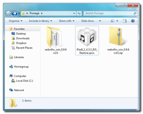
Create a folder on your desktop called Pwnage

Download RedSn0w from here and place it in the Pwnage folder. Likewise, download the latest 4.3.3 firmware from below and place it in the same folder.

4.3.3 (iPad 1): iPad1,1_4.3.3_8J3_Restore.ipsw

Extract the RedSn0w zip file into the same folder.


Step Two
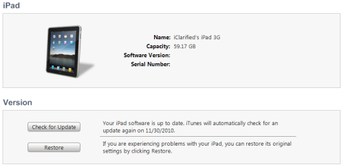
Connect your iPad to the computer and launch iTunes.


Select your iPad from the list of devices on the left. Now hold down Shift and click the Restore button. Restore is preferred as it won't create any wasted space on your iPad.

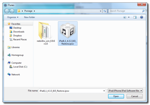
Navigate to the Pwnage folder on your desktop and select the 4.3.3 firmware ipsw. Click the Choose button to continue.


Step Three
Once iTunes has finished updating your iPad to the desired firmware open the Pwnage folder on your desktop and launch the redsn0w application from the redsn0w folder we extracted earlier.

**Windows 7 users may need to run RedSn0w in Vista Compatibility mode. You can do this by right clicking the executable and selecting Properties from the contextual menu.


Step Four
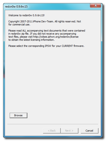
Once RedSn0w opens click the Browse button


Step Five
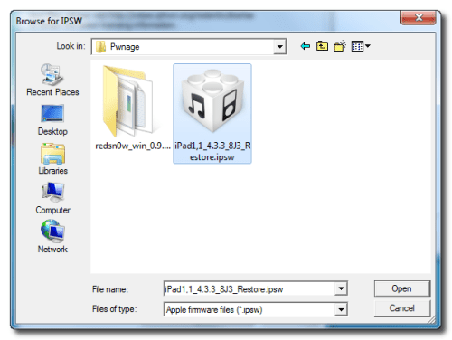
Select the 4.3.3 firmware ipsw we placed in the Pwnage folder on our desktop then click Open.


Step Six
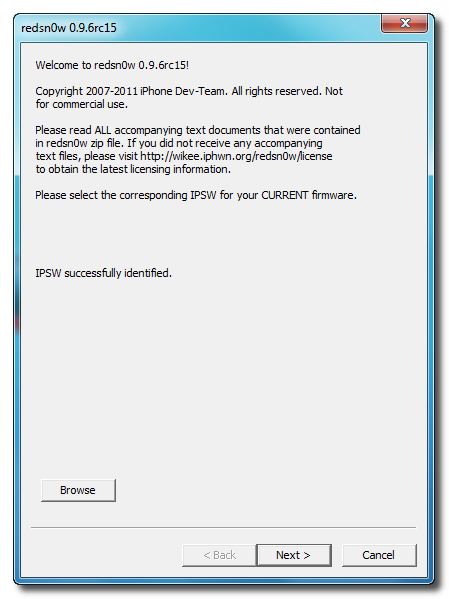
Once the firmware has been verified click the Next button to continue.


Step Seven
RedSn0w will now prepare the jailbreak data


Step Eight
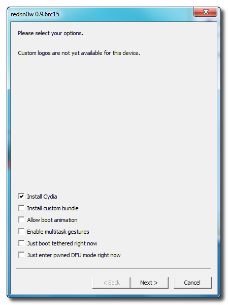
From this window you can select the jailbreak options you would like. Make sure Cydia is selected and click the Next button to continue.


Step Nine
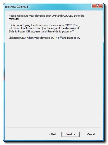
Please plug your iPad into the computer and make sure its OFF then click the Next button


Step Ten
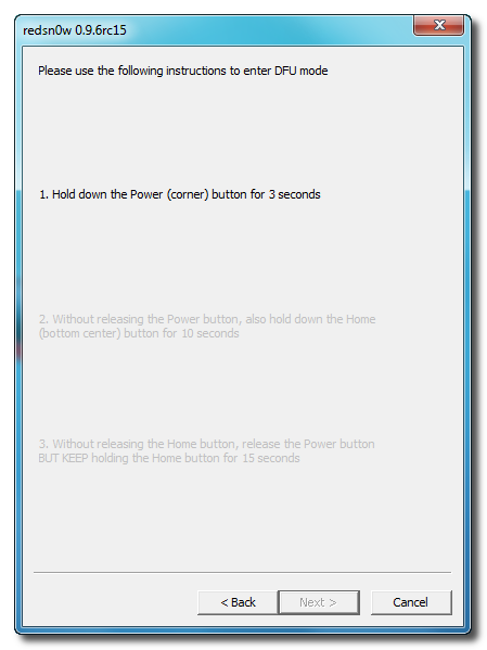
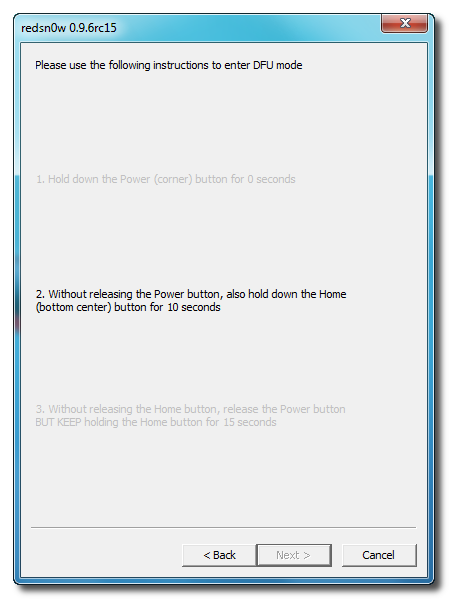
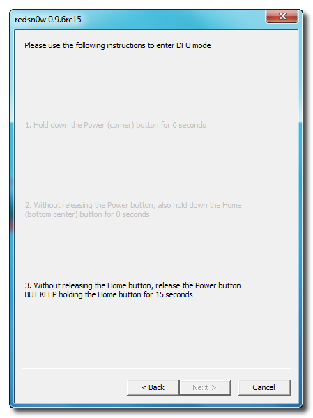
RedSn0w will now guide you through the steps to get into DFU mode. You can find more help with DFU mode here


Hold down both the Home button and the Power button for 10 seconds.


Release the Power button and continue holding the Home button until RedSn0w detects the device.


Step Eleven
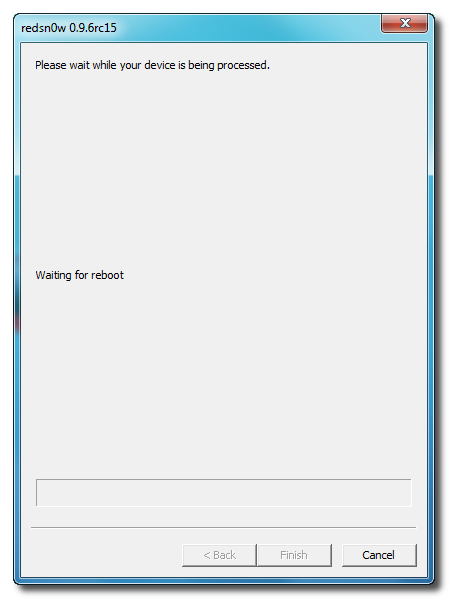
Your iPad will now reboot


Step Twelve
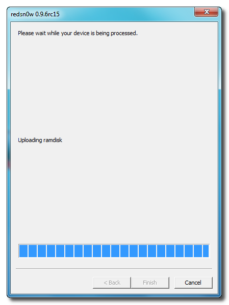
RedSn0w will then begin uploading the new RAM Disk and Kernel.


Step Thirteen
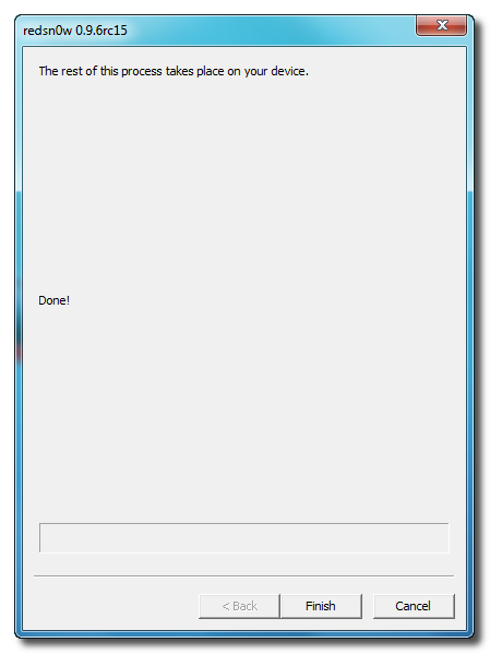
Once this is complete you will be notified that RedSn0w is done. Click the Finish button. When your iPad finishes rebooting (5 minutes or so) it will be jailbroken with Cydia on the SpringBoard.

iPhone | How to Enable iCloud Automatic Downloads in iOS

These are instructions on how to enable iCloud Automatic Downloads for Apps, iTunes, and iBooks in iOS. You need an iTunes account to enable this new feature.  


http://www.youtube.com/watch?feature=player_embedded&v=4LvJ9MyWKQ0
Step One
Press to launch Settings from your Springboard.


Step Two
Press to select Store from the Settings Menu.


Step Three
Press the Sign In button if you are not already Signed In.


Step Four
To enable Automatic Downloads for Apps, iTunes, or iBooks turn the respective switch to the ON position.

To enable Automatic Downloads while you are on the cellular network turn the Cellular switch to the ON position.


Now when you purchase or download a new app, song, or book the item will automatically be pushed to all your devices.

Tuesday, June 7, 2011

How to Jailbreak Your iPhone 4 Using RedSn0w (Windows) [4.3.3]

Step One
Create a folder on your desktop called Pwnage

Download RedSn0w from here and place it in the Pwnage folder. Likewise, download the latest 4.3.3 firmware from below and place it in the same folder.

4.3.3 (4 GSM): iPhone3,1_4.3.3_8J2_Restore.ipsw

Extract the RedSn0w zip file into the same folder.


Step Two
Connect your iPhone to the computer and launch iTunes.


Select your iPhone from the list of devices on the left. Now hold down Shift and click the Restore button. Restore is preferred as it won't create any wasted space on your iPhone.


Navigate to the Pwnage folder on your desktop and select the 4.3.3 firmware ipsw. Click the Choose button to continue.


Step Three
Once iTunes has finished updating your iPhone to the desired firmware open the Pwnage folder on your desktop and launch the redsn0w application from the redsn0w folder we extracted earlier.

**Windows 7 users may want to try running the redsn0w executable mode as an administrator in Windows Vista compatibility. You can do this by right clicking the executable and selecting Properties from the contextual menu.


Step Four
Once RedSn0w opens click the Browse button


Step Five
Select the 4.3.3 firmware ipsw we placed in the Pwnage folder on our desktop then click Open.


Step Six
Once the firmware has been verified click the Next button to continue.


Step Seven
RedSn0w will now prepare the jailbreak data


Step Eight
From this window you can select the jailbreak options you would like.

Make sure Cydia is selected and click the Next button to continue.


Step Nine
Please plug your iPhone into the computer and make sure its OFF then click the Next button


Step Ten
RedSn0w will now guide you through the steps to get into DFU mode. You can find more help with DFU mode here


Hold down both the Home button and the Power button for 10 seconds.


Release the Power button and continue holding the Home button until RedSn0w detects the device.


Step Eleven
Your iPhone will now reboot


Step Twelve
RedSn0w will then begin uploading the new RAM Disk and Kernel.


Step Thirteen
Once this is complete you will be notified that RedSn0w is done. Click the Finish button. When your iPhone finishes rebooting (5 minutes or so) it will be jailbroken with Cydia on the SpringBoard.