

Transistor as a switch
The transistor actually works as a current gainer; any current applied to the base terminal will be multiplied by the current gain factor of the transistor which known as hFE. Therefore transistor can be used as amplifier; any small signal (very small current) applied to the base terminal will be amplified by the factor of hFE and reflected as a collector current on the collector terminal side.

All the transistors have three state of operation:
- Off state: in this state there is no base current applied or IB = 0.
- On active state: in this state any changes in IB will cause changes in IC as well or IC = IB x hFE. This type of state is suitable when we use transistor as a signal amplifier because transistor is said is in the linear state. For example if we have a transistor with gain of 100 and we increase the IB from 10uA to 100uA; this will cause the IC to swing from 1000uA to 10000uA (1 mA to 10 mA).
- On saturate state: in this state any changes in IB will not cause changes in IC anymore (not linear) or we could say IC is nearly constant. We never use this state to run the transistor as a signal amplifier (class A amplifier) because the output signal will be clamped when the transistor is saturate. This is the type of state that we are looking for on this tutorial.
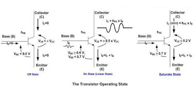
From the picture above we could see the voltage and current condition of transistor on each state; if you notice when transistor is in off state the voltage across collector and emitter terminal is equal to the supplied voltage, this is equivalent to the open circuit and when transistor is in saturate state the collector to emitter voltage is equal or less then 0.2 Volt which is equivalent to the close circuit. Therefore to use transistor as a switch we have to make transistor OFF which equivalent to the logical “0” and SATURATE which is equivalent to the logical “1“.

The above diagram show a typical microcontroller interface circuit using NPN transistor; the RB resistor is used to control the current on base terminal that make transistor OFF and ON (saturate); while the RC resistor is the current limiter for the load. if the load operate with the same voltage as the supplied power (Vcc) you can by pass the RC (not use).
Notice the diode (also known as the clamp diode) in the inductive load circuit is needed to protect the transistor again the EMF (Electromotive Force) voltage generated by the inductor component when the transistor is switched on and off rapidly, this voltage is oppose the source voltage. The diode will act as a short circuit to the high voltage generated by the inductor component, you can use any general purpose diode with capable on handling minimum 1 A of current such as 1N4001, 1N4002, etc.
Ok let’s calculate each of the RB and RC value on this following.......

On the circuit above we are going to use 2N3904 (the cheap general purpose transistor where you could easily found on your local market) to drive 5 LED from microcontroller port, from the 2N3904 datasheet we get this information:
IC max = 200mA (this is maximum value that will make your transistor smoked, for more practical application always use just half of the maximum value mentioned on the datasheet), hFE = 100 to 300, VBE saturate = 0.65 Volt, VCE saturate = 0.2 Volt
For most transistor in general we can use VBE = 0.7 Volt (should be saturate) and VCE = 0 Volt. Using the 5 volt power supply (VCC) and assuming VLED = 2 Volt, with each of them consuming 15 mA, we could calculate the RC value using the Ohm’s law as follow:
IC = 5 x 15 mA = 75mA (0.075 A), this current is still far bellow the maximum IC allowed by 2N3904 transistor.
RC = (VCC - VLED) / IC = (5 - 2) / 0.075 = 40 Ohm
Power Dissipation on the RC resistor will be
P = (VCC - VLED) x IC = (5 - 2) x 0.075 = 0.225 Watt
Base on the above calculation we could use the nearest higher value available on the market; which is 47 Ohm, 0.5 watt resistor (for heat dissipation usually we use twice of the watt value calculated).
With the hFE minimum of 100; the minimum current required in the transistor’s base terminal to drive the LED is:
IC = hFE x IB
IB = IC / hFE = 0.075 / 100 = 0.00075 A (0.75 mA)
This current can easily be supplied by most microcontroller I/O port; which is capable to drive up to 20 mA output current. Again by applying the Ohm’s law we could calculate the RB value as follow:
RB = (VPORT - VBE) / IB
Assuming the minimum average voltage of microcontroller I/O port (VPORT) with logical “1” is about 4.2 volt (the microcontroller is powered by 5 volt supply):
RB = (4.2 - 0.7) / 0.00075 = 4666.66 Ohm
Power dissipation on the RC resistor will be
P = (VPORT - VBE) x IB = (4.2 - 0.7) x 0.00075 = 0.002625 Watt
Base on the result you could use 4K7 Ohm, 0.25 Watt resistor (this is the common resistor which you could easily found on the local market i.e. 0.25 watt and 0.5 watt).
Use this RB calculation as your maximum reference value; in the real world most of the transistors hFE is vary and being measured (tested) with different VCE and IC value not to mention different specification even though you use the same transistor type. Therefore the real RB value could be lower than 4K7 if you really want to drive the transistor into fully saturate mode where the VCE near 0.2 volt.
Below is an example of driving ac load through relay with a transistor......

Comparator as ADC
Sometimes in the embedded system world we need to process the analog world and sending the signal to the microcontroller when the analog signal exceed some predetermine limit we’ve set. Some example of this situation is to send the interrupt signal to the microcontroller operation when the temperature is already exceeds certain limit or the light intensity exceeds certain bright level. This is when the comparator circuit becomes handy as it’s designed specially for this purpose.
Today the modern comparator is easily found in the form of integrated circuit such as the popular National Semiconductor LM339 or LM324 quad (four) comparator 14 pins dual in line (DIL) package bellow:

1. Basic Comparator Circuit
The comparator circuit work by simply taking two analog inputs, comparing them and produce the logical output high “1” or low “0“.

By applying the analog signal to the comparator + input called “non-inverting” and - input called “inverting“, the comparator circuit will compared this two analog signal, if the analog input on + input is greater than the analog input on - input (inverting) then the output will swing to the logical “1” and this will make the open collector transistor Q8 on the LM339 equivalent circuit above to turn ON. When the analog input on + input (non inverting) is less than the analog input on - input (inverting) then the comparator output will swing to the logical “0” (the Q8 transistor turn OFF). Furthermore on this tutorial, I will use the term non-inverting and inverting instead of + input and - input on the comparator analog input.

The testing circuit simply connects the comparator inverting input to the voltage divider R1 and R2, with 5 Volt voltage supply the V- could be calculated as follow:
V- = (R2 / (R1 + R2)) x Vcc
V- = (10 / 20) x 5 volt = 2.5 volt

The above fig show how analog signal is converted to Digital
Sensor using Comparator

When the infra-red LED beam reflected back to the photo transistor, the photo transistor will turn ON; this will make the reference voltage ( V+) become greater than the input voltage (V-). This condition will make the comparator give a logical high to the microcontroller I/O port. When the infra-red LED beam is blocked, the photo transistor will turn OFF; this will make the input voltage (V-) become greater than the reference voltage (V+) and the comparator will give a logical low to the microcontroller I/O port.
Hmm, by applying the circuit schema above to all the comparators in the LM339 package (four comparators), we could make a very sensitive infrared reflector sensors for sensing the black/white line used in many line follower or line maze solver robot.
No comments:
Post a Comment